Aluminum foil heating film, with its unique performance advantages of efficient and uniform heating, energy saving and safety, lightweight and flexibility, has shown a significant acceleration in demand in multiple high growth fields, especially in the following industries and application scenarios:
New energy vehicles and thermal management of power batteries
The explosive growth of the new energy vehicle industry (with the global penetration rate of electric vehicles continuing to rise) directly drives the large-scale application of aluminum foil heating films in battery thermal management systems (BTMS) and cabin comfort configurations
1.Heating and insulation of power batteries:
The charging and discharging efficiency of lithium-ion batteries significantly decreases in low-temperature environments (below 0 ° C), which may even lead to battery life degradation or performance failure. Aluminum foil heating film has become a key solution to solve the problem of low-temperature start-up due to its uniform heating characteristics and fast response ability (heating up within a few minutes of power on):
- Battery pack heating layer: adheres to the surface or gap of the battery module, and provides heat as needed through an intelligent temperature control system to ensure that the battery can maintain its optimal working temperature (usually 15-35 ° C) under extreme cold conditions, improving range and charging efficiency.
- Energy density improvement and lightweight requirements: The ultra-thin and flexible design of aluminum foil film (with a thickness of only micrometers) can seamlessly fit the curved surface of the battery pack, without occupying additional space, meeting the strict requirements of new energy vehicles for weight reduction and efficiency improvement. At the same time, compared with traditional PTC ceramic heating solutions, its thermal conversion efficiency is higher (with an energy conversion rate of over 95%) and its heat uniformity is better, which is more in line with the refined thermal management needs of high-voltage platforms (such as 800V systems).
2.Cabin comfort configuration:
Electric vehicles have no engine waste heat utilization, leading to a surge in demand for independent heating systems:
- Seat/steering wheel heating: The lightweight and flexible aluminum foil heating film can be perfectly embedded into the interior structure, providing a uniform and warm experience;
- Rearview mirror/windshield defrosting: fast and efficient surface heating design ensures clear driving vision;
- Air conditioning preheating system: accelerates cabin heating in cold climates to optimize user experience.
- Market size and growth: According to industry estimates, the annual compound growth rate of the new energy vehicle thermal management system market is as high as about 30%. The demand for power battery heating and cabin comfort is the core growth engine, directly driving the explosive growth of demand for aluminum foil heating film in this field.
Building heating and intelligent temperature control field
Energy saving upgrade and policy driven demand surge:
Aluminum foil heating film is gradually replacing traditional water heating or resistance wire solutions with its efficient and uniform heating, intelligent integration, and fast response characteristics, becoming the mainstream choice in the field of building heating.
1.Electric underfloor heating system:
- Advantages of surface heating: The high thermal conductivity of the aluminum foil layer enables uniform heat transfer to the entire floor, with a fast heating rate (heating can be achieved in a few minutes) and a small temperature gradient, significantly improving indoor thermal comfort, especially suitable for temperature sensitive elderly, children, and commercial places.
- Energy saving and intelligent control: With high energy conversion efficiency (over 95%), combined with intelligent systems such as zone temperature control and remote APP operation, energy consumption can be adjusted as needed, meeting the requirements of global carbon neutrality goals and building energy conservation policies of various countries (such as China's "dual carbon" policy and the EU ErP directive) for efficient heating.
- Installation convenience: The ultra-thin flexible film can be directly laid under the floor or wall without the need for complex pipeline systems, greatly reducing construction costs and time, especially suitable for the renovation of old houses and the high-end decoration market.
2.Pipeline heat tracing and anti freezing insulation:
In cold regions such as Northeast and Northern Europe, it is used for anti freezing insulation of water supply pipelines and oil and gas pipelines. Compared with traditional heat tracing, aluminum foil heating film is lighter, easier to install, and has lower maintenance costs. At the same time, it can provide more stable heat distribution and prevent local freezing and cracking risks.
- Growth trend: With the increasing demand of consumers for comfort, energy efficiency, and smart homes, as well as the continuous increase in the penetration rate of electric heating in areas with insufficient coverage of central heating, the demand growth rate of aluminum foil heating film in the construction industry is significantly higher than the industry average.
In the field of consumer electronics and home appliance upgrading
Emerging application scenarios continue to expand, and demand diversification is exploding
1.Wearable devices and healthcare:
- Heating knee pads, warm gloves, intelligent wearable heating elements: Aluminum foil heating film can be flexibly cut into any shape, fitting the curved surfaces of human joints, wrists, etc., providing close fitting and precise local heating, meeting the needs of outdoor enthusiasts, sports rehabilitation groups, and middle-aged and elderly consumers for thermal treatment. Its flexible design (bending resistance, water washing) and safety (insulation layer protection) make it an ideal choice for wearable heating devices.
- Emerging market potential: By combining technologies such as biosensors and temperature control chips, innovative products such as intelligent heating therapy belts and hot compress patches can be developed, which are in line with the trend of upgrading health consumption.
2.Home appliance auxiliary heating:
- Refrigerator defrosting/thawing: Suitable for the surface of the evaporator in the refrigeration compartment, precise temperature control to prevent frosting, replacing traditional electric heating wires, improving refrigeration efficiency and reducing energy consumption;
- Air conditioning preheating and dehumidification: accelerate the temperature rise of the air conditioning during cold seasons, or assist in dehumidification in humid environments;
- Clothes dryer, electric heating table, beauty equipment: The large-area and uniform heating design ensures efficient operation and can be seamlessly embedded into the narrow space inside the equipment.
3.Electronic Manufacturing and Precision Devices:
In the production of semiconductors and electronic components, it is used to heat workbenches, solidify adhesive layers, or maintain a constant temperature environment for precision instruments. Its surface heating characteristics avoid damage to sensitive components caused by local overheating, while also adapting to special environmental requirements such as clean rooms.
- Market performance: The rapid growth of sub sectors such as wearable devices and smart homes directly drives the exponential growth of demand for aluminum foil heating films in the consumer electronics field, especially in emerging markets such as Southeast Asia and Latin America where penetration rates have significantly increased.
Industrial and Special Application Fields
Technological upgrades and green transformation drive steady growth in demand
1.Industrial insulation and drying:
- Pipeline and equipment anti freezing and heat tracing: In the petroleum, chemical, and pharmaceutical industries, there is a continuous demand for anti freezing and insulation of long-distance transportation pipelines (such as crude oil and chemicals). The lightweight and uniform heat advantages of aluminum foil heating films are gradually replacing traditional heat tracing belts;
- Oven and drying equipment: used for drying processes in printing, food processing, building materials production, and other fields, ensuring uniform heating of materials, improving product yield, and lower energy consumption and easier maintenance compared to resistance wire heating.
2.Medical and laboratory equipment:
- Blood analyzers, incubators, and therapy equipment: It is necessary to maintain a constant temperature environment to ensure sample activity or treatment effectiveness. The uniform heating characteristics (minimal temperature fluctuations), biocompatibility (environmentally friendly material), and safety of aluminum foil heating film make it the preferred solution for thermal management of medical equipment;
- Portable medical devices, such as heated infusion bags, temperature controlled emergency kits, etc., utilize their lightweight and flexible characteristics to achieve portable design.
3.Aerospace and military industry:
- applied in scenarios such as aircraft wing de icing, cockpit insulation, and military equipment anti freezing, requiring materials to be resistant to high temperatures and extreme environments (such as high pressure and radiation). Aluminum foil heating film can meet such high reliability requirements through structural optimization (multi-layer protection) and special conductive materials (such as graphene coating), with huge potential but currently low penetration rate.
Emerging high potential fields (future incremental focus)
1.Flexible electronics and foldable devices:
- With the development of foldable screen phones and flexible display technology, aluminum foil heating film can be integrated as a flexible heating layer inside the device to solve the problem of screen response delay or material brittleness in low-temperature environments, without affecting the bending performance of the product.
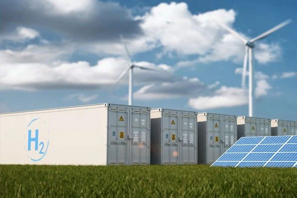
2.Energy storage and new energy matching:
- In addition to power batteries, the thermal management needs of energy storage power stations, photovoltaic inverters and other equipment are gradually emerging. Aluminum foil heating film can be used for battery cluster heating, temperature control system auxiliary heat dissipation and other scenarios, benefiting from the rapid expansion of global energy storage installed capacity.
3.Agriculture and greenhouse cultivation:
- In facility agriculture, it is used for soil heating, seedling box temperature control, irrigation pipeline antifreeze, etc. Its high-efficiency and energy-saving characteristics meet the needs of modern agriculture for refined temperature control and cost control, especially in high value-added crop planting areas such as strawberries and flowers, where the market potential is considerable.
Summary: Four Golden Races and Potential Extension
Overall, the areas with the fastest growth in demand for aluminum foil heating film are:
- New energy vehicles (thermal management of power batteries and cabin comfort) - the core beneficiary track of the global electric vehicle industry explosion;
- Building heating and pipeline heating - a deterministic growth market driven by policies and consumer upgrades;
- Consumer electronics and wearable devices - the demand blue ocean generated by the diversification of emerging application scenarios;
- Industrial insulation and medical equipment - a steady growth field driven by the demand for technological substitution and refinement.
In the future, with the gradual penetration of emerging scenarios such as flexible electronics, energy storage matching, and agricultural temperature control, the market boundary of aluminum foil heating film will continue to expand, and its strategic position in the field of efficient thermal management solutions will become increasingly prominent. For enterprises, focusing on the high growth track mentioned above, strengthening technological innovation (such as new conductive materials, intelligent integration), and global layout will be the key to seizing market opportunities.